2. Genesis
3. The Screen
4. The GDT and IDT
5. IRQs and the PIT
6. Paging
7. The Heap
8. The VFS and the initrd
9. Multitasking
10. User Mode
4. The GDT and IDT
The GDT and the IDT are descriptor tables. They are arrays of flags and bit values describing the operation of either the segmentation system (in the case of the GDT), or the interrupt vector table (IDT).
They are, unfortunately, a little theory-heavy, but bear with it because it'll be over soon!
4.1. The Global Descriptor Table (theory)
The x86 architecture has two methods of memory protection and of providing virtual memory - segmentation and paging.
With segmentation, every memory access is evaluated with respect to a segment. That is, the memory address is added to the segment's base address, and checked against the segment's length. You can think of a segment as a window into the address space - The process does not know it's a window, all it sees is a linear address space starting at zero and going up to the segment length.
With paging, the address space is split into (usually 4KB, but this can change) blocks, called pages. Each page can be mapped into physical memory - mapped onto what is called a 'frame'. Or, it can be unmapped. Like this you can create virtual memory spaces.
Both of these methods have their advantages, but paging is much better. Segmentation is, although still usable, fast becoming obsolete as a method of memory protection and virtual memory. In fact, the x86-64 architecture requires a flat memory model (one segment with a base of 0 and a limit of 0xFFFFFFFF) for some of it's instructions to operate properly.
Segmentation is, however, totally in-built into the x86 architecture. It's impossible to get around it. So here we're going to show you how to set up your own Global Descriptor Table - a list of segment descriptors.
As mentioned before, we're going to try and set up a flat memory model. The segment's window should start at 0x00000000 and extend to 0xFFFFFFFF (the end of memory). However, there is one thing that segmentation can do that paging can't, and that's set the ring level.
A ring is a privilege level - zero being the most privileged, and three being the least. Processes in ring zero are said to be running in kernel-mode, or supervisor-mode, because they can use instructions like sti and cli, something which most processes can't. Normally, rings 1 and 2 are unused. They can, technically, access a greater subset of the supervisor-mode instructions than ring 3 can. Some microkernel architectures use these for running server processes, or drivers.
A segment descriptor carries inside it a number representing the ring level it applies to. To change ring levels (which we'll do later on), among other things, we need segments that represent both ring 0 and ring 3.[3.2.4]
4.2. The Global Descriptor Table (practical)
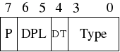
Access byte format
One thing I forgot to mention is that GRUB sets a GDT up for you. The problem is that you don't know where that GDT is, or what's in it. So you could accidentally overwrite it, then your computer would triple-fault and reset. Not clever.
In the x86, we have 6 segmentation registers. Each holds an offset into the GDT. They are cs (code segment), ds (data segment), es (extra segment), fs, gs, ss (stack segment). The code segment must reference a descriptor which is set as a 'code segment'. There is a flag for this in the access byte. The rest should all reference a descriptor which is set as a 'data segment'.
4.2.1. descriptor_tables.h
A GDT entry looks like this:
// We use the attribute 'packed' to tell GCC not to change
// any of the alignment in the structure.
struct gdt_entry_struct
{
u16int limit_low; // The lower 16 bits of the limit.
u16int base_low; // The lower 16 bits of the base.
u8int base_middle; // The next 8 bits of the base.
u8int access; // Access flags, determine what ring this segment can be used in.
u8int granularity;
u8int base_high; // The last 8 bits of the base.
} __attribute__((packed));
typedef struct gdt_entry_struct gdt_entry_t;
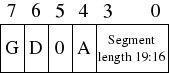
Granularity byte format
P
Is segment present? (1 = Yes)
DPL
Descriptor privilege level - Ring 0 - 3.
DT
Descriptor type
Type
Segment type - code segment / data segment.
G
Granularity (0 = 1 byte, 1 = 1kbyte)
D
Operand size (0 = 16bit, 1 = 32bit)
0
Should always be zero.
A
Available for system use (always zero).
To tell the processor where to find our GDT, we have to give it the address of a special pointer structure:
{
u16int limit; // The upper 16 bits of all selector limits.
u32int base; // The address of the first gdt_entry_t struct.
}
__attribute__((packed));
typedef struct gdt_ptr_struct gdt_ptr_t;
The base is the address of the first entry in our GDT, the limit being the size of the table minus one (the last valid address in the table).
Those struct definitions should go in a header file, descriptor_tables.h, along with a prototype.
void init_descriptor_tables();
4.2.2. descriptor_tables.c
In descriptor_tables.c, we have a few declarations:
// descriptor_tables.c - Initialises the GDT and IDT, and defines the
// default ISR and IRQ handler.
// Based on code from Bran's kernel development tutorials.
// Rewritten for JamesM's kernel development tutorials.
//
#include "common.h"
#include "descriptor_tables.h"
// Lets us access our ASM functions from our C code.
extern void gdt_flush(u32int);
// Internal function prototypes.
static void init_gdt();
static void gdt_set_gate(s32int,u32int,u32int,u8int,u8int);
gdt_entry_t gdt_entries[5];
gdt_ptr_t gdt_ptr;
idt_entry_t idt_entries[256];
idt_ptr_t idt_ptr;
Notice the gdt_flush function - this will be defined in an ASM file, and will load our GDT pointer for us.
// initialises the GDT and IDT.
void init_descriptor_tables()
{
// Initialise the global descriptor table.
init_gdt();
}
static void init_gdt()
{
gdt_ptr.limit = (sizeof(gdt_entry_t) * 5) - 1;
gdt_ptr.base = (u32int)&gdt_entries;
gdt_set_gate(0, 0, 0, 0, 0); // Null segment
gdt_set_gate(1, 0, 0xFFFFFFFF, 0x9A, 0xCF); // Code segment
gdt_set_gate(2, 0, 0xFFFFFFFF, 0x92, 0xCF); // Data segment
gdt_set_gate(3, 0, 0xFFFFFFFF, 0xFA, 0xCF); // User mode code segment
gdt_set_gate(4, 0, 0xFFFFFFFF, 0xF2, 0xCF); // User mode data segment
gdt_flush((u32int)&gdt_ptr);
}
// Set the value of one GDT entry.
static void gdt_set_gate(s32int num, u32int base, u32int limit, u8int access, u8int gran)
{
gdt_entries[num].base_low = (base & 0xFFFF);
gdt_entries[num].base_middle = (base >> 16) & 0xFF;
gdt_entries[num].base_high = (base >> 24) & 0xFF;
gdt_entries[num].limit_low = (limit & 0xFFFF);
gdt_entries[num].granularity = (limit >> 16) & 0x0F;
gdt_entries[num].granularity |= gran & 0xF0;
gdt_entries[num].access = access;
}
Lets just analyse that code for a moment. init_gdt initially sets up the gdt pointer structure - the limit is the size of each gdt entry * 5 - we have 5 entries. Why 5? well, we have a code and data segment descriptor for the kernel, code and data segment descriptors for user mode, and a null entry. This must be present, or bad things will happen.
gdt_init then sets up the 5 descriptors, by calling gdt_set_gate. gdt_set_gate just does some severe bit-twiddling and shifting, and should be self-explanatory with a hard stare at it. Notice that the only thing that changes between the 4 segment descriptors is the access byte - 0x9A, 0x92, 0xFA, 0xF2. You can see, if you map out the bits and compare them to the format diagram above, the bits that are changing are the type and DPL fields. DPL is the descriptor privilege level - 3 for user code and 0 for kernel code. Type specifies whether the segment is a code segment or a data segment (the processor checks this often, and can be the source of much frustration).
Finally, we have our ASM function that will write the GDT pointer.
gdt_flush:
mov eax, [esp+4] ; Get the pointer to the GDT, passed as a parameter.
lgdt [eax] ; Load the new GDT pointer
mov ax, 0x10 ; 0x10 is the offset in the GDT to our data segment
mov ds, ax ; Load all data segment selectors
mov es, ax
mov fs, ax
mov gs, ax
mov ss, ax
jmp 0x08:.flush ; 0x08 is the offset to our code segment: Far jump!
.flush:
ret
This function takes the first parameter passed to it (in esp+4), loads the value is points to into the GDT (using the lgdt instruction), then loads the segment selectors for the data and code segments. Notice that each GDT entry is 8 bytes, and the kernel code descriptor is the second segment, so it's offset is 0x08. Likewise the kernel data descriptor is the third, so it's offset is 16 = 0x10. Here we move the value 0x10 into the data segment registers ds,es,fd,gs,ss. To change the code segment is slightly different; we must do a far jump. This changes the CS implicitly.
4.3. The Interrupt Descriptor Table (theory)
There are times when you want to interrupt the processor. You want to stop it doing what it is doing, and force it to do something different. An example of this is when an timer or keyboard interrupt request (IRQ) fires. An interrupt is like a POSIX signal - it tells you that something of interest has happened. The processor can register 'signal handlers' (interrupt handlers) that deal with the interrupt, then return to the code that was running before it fired. Interrupts can be fired externally, via IRQs, or internally, via the 'int n' instruction. There are very useful reasons for wanting to do fire interrupts from software, but that's for another chapter!
The Interrupt Descriptor Table tells the processor where to find handlers for each interrupt. It is very similar to the GDT. It is just an array of entries, each one corresponding to an interrupt number. There are 256 possible interrupt numbers, so 256 must be defined. If an interrupt occurs and there is no entry for it (even a NULL entry is fine), the processor will panic and reset.
4.3.1. Faults, traps and exceptions
The processor will sometimes need to signal your kernel. Something major may have happened, such as a divide-by-zero, or a page fault. To do this, it uses the first 32 interrupts. It is therefore doubly important that all of these are mapped and non-NULL - else the CPU will triple-fault and reset (bochs will panic with an 'unhandled exception' error).
The special, CPU-dedicated interrupts are shown below.
- 0 - Division by zero exception
- 1 - Debug exception
- 2 - Non maskable interrupt
- 3 - Breakpoint exception
- 4 - 'Into detected overflow'
- 5 - Out of bounds exception
- 6 - Invalid opcode exception
- 7 - No coprocessor exception
- 8 - Double fault (pushes an error code)
- 9 - Coprocessor segment overrun
- 10 - Bad TSS (pushes an error code)
- 11 - Segment not present (pushes an error code)
- 12 - Stack fault (pushes an error code)
- 13 - General protection fault (pushes an error code)
- 14 - Page fault (pushes an error code)
- 15 - Unknown interrupt exception
- 16 - Coprocessor fault
- 17 - Alignment check exception
- 18 - Machine check exception
- 19-31 - Reserved
4.4. The Interrupt Descriptor Table (practice)
4.4.1. descriptor_tables.h
We should add some definitions to descriptor_tables.h:
struct idt_entry_struct
{
u16int base_lo; // The lower 16 bits of the address to jump to when this interrupt fires.
u16int sel; // Kernel segment selector.
u8int always0; // This must always be zero.
u8int flags; // More flags. See documentation.
u16int base_hi; // The upper 16 bits of the address to jump to.
} __attribute__((packed));
typedef struct idt_entry_struct idt_entry_t;
// A struct describing a pointer to an array of interrupt handlers.
// This is in a format suitable for giving to 'lidt'.
struct idt_ptr_struct
{
u16int limit;
u32int base; // The address of the first element in our idt_entry_t array.
} __attribute__((packed));
typedef struct idt_ptr_struct idt_ptr_t;
// These extern directives let us access the addresses of our ASM ISR handlers.
extern void isr0 ();
...
extern void isr31();
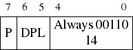
Flags byte format
4.4.2. descriptor_tables.c
We need to modify this file to add our new code.
extern void idt_flush(u32int);
...
static void init_idt();
static void idt_set_gate(u8int,u32int,u16int,u8int);
...
idt_entry_t idt_entries[256];
idt_ptr_t idt_ptr;
...
void init_descriptor_tables()
{
init_gdt();
init_idt();
}
...
static void init_idt()
{
idt_ptr.limit = sizeof(idt_entry_t) * 256 -1;
idt_ptr.base = (u32int)&idt_entries;
memset(&idt_entries, 0, sizeof(idt_entry_t)*256);
idt_set_gate( 0, (u32int)isr0 , 0x08, 0x8E);
idt_set_gate( 1, (u32int)isr1 , 0x08, 0x8E);
...
idt_set_gate(31, (u32int)isr32, 0x08, 0x8E);
idt_flush((u32int)&idt_ptr);
}
static void idt_set_gate(u8int num, u32int base, u16int sel, u8int flags)
{
idt_entries[num].base_lo = base & 0xFFFF;
idt_entries[num].base_hi = (base >> 16) & 0xFFFF;
idt_entries[num].sel = sel;
idt_entries[num].always0 = 0;
// We must uncomment the OR below when we get to using user-mode.
// It sets the interrupt gate's privilege level to 3.
idt_entries[num].flags = flags /* | 0x60 */;
}
This gets added to gdt.s also:
idt_flush:
mov eax, [esp+4] ; Get the pointer to the IDT, passed as a parameter.
lidt [eax] ; Load the IDT pointer.
ret
4.4.3. interrupt.s
Great! We've got code that will tell the CPU where to find our interrupt handlers - but we haven't written any yet!
When the processor receives an interrupt, it saves the contents of the essential registers (instruction pointer, stack pointer, code and data segments, flags register) to the stack. It then finds the interrupt handler location from our IDT and jumps to it.
Now, just like POSIX signal handlers, you don't get given any information about what interrupt was called when your handler is run. So, unfortunately, we can't just have one common handler, we must write a different handler for each interrupt we want to handle. This is pretty crap, so we want to keep the amount of duplicated code to a minimum. We do this by writing many handlers that just push the interrupt number (hardcoded in the ASM) onto the stack, and call a common handler function.
That's all gravy, but unfortunately, we have another problem - some interrupts also push an error code onto the stack. We can't call a common function without a common stack frame, so for those that don't push an error code, we push a dummy one, so the stack is the same.
isr0:
cli ; Disable interrupts
push byte 0 ; Push a dummy error code (if ISR0 doesn't push it's own error code)
push byte 0 ; Push the interrupt number (0)
jmp isr_common_stub ; Go to our common handler.
That sample routine will work, but 32 versions of that still sounds like a lot of code. We can use NASM's macro facility to cut this down, though:
[GLOBAL isr%1] ; %1 accesses the first parameter.
isr%1:
cli
push byte 0
push byte %1
jmp isr_common_stub
%endmacro
%macro ISR_ERRCODE 1
[GLOBAL isr%1]
isr%1:
cli
push byte %1
jmp isr_common_stub
%endmacro
We can now make a stub handler function just by doing
ISR_NOERRCODE 1
...
Much less work, and anything that makes our lives easier is worth doing. A quick look at the intel manual will tell you that only interrupts 8, 10-14 inclusive push error codes onto the stack. The rest require dummy error codes.
We're almost there, I promise!
Only 2 more things left to do - one is to create an ASM common handler function. The other is to create a higher-level C handler function.
[EXTERN isr_handler]
; This is our common ISR stub. It saves the processor state, sets
; up for kernel mode segments, calls the C-level fault handler,
; and finally restores the stack frame.
isr_common_stub:
pusha ; Pushes edi,esi,ebp,esp,ebx,edx,ecx,eax
mov ax, ds ; Lower 16-bits of eax = ds.
push eax ; save the data segment descriptor
mov ax, 0x10 ; load the kernel data segment descriptor
mov ds, ax
mov es, ax
mov fs, ax
mov gs, ax
call isr_handler
pop eax ; reload the original data segment descriptor
mov ds, ax
mov es, ax
mov fs, ax
mov gs, ax
popa ; Pops edi,esi,ebp...
add esp, 8 ; Cleans up the pushed error code and pushed ISR number
sti
iret ; pops 5 things at once: CS, EIP, EFLAGS, SS, and ESP
This piece of code is our common interrupt handler. It firstly uses the 'pusha' command to push all the general purpose registers on the stack. It uses the 'popa' command to restore them at the end. It also gets the current data segment selector and pushes that onto the stack, sets all the segment registers to the kernel data selector, and restores them afterwards. This won't actually have an effect at the moment, but it will when we switch to user-mode. Notice it also calls a higher-level interrupt handler - isr_handler.
When an interrupt fires, the processor automatically pushes information about the processor state onto the stack. The code segment, instruction pointer, flags register, stack segment and stack pointer are pushed. The IRET instruction is specifically designed to return from an interrupt. It pops these values off the stack and returns the processor to the state it was in originally.
4.4.4. isr.c
// isr.c -- High level interrupt service routines and interrupt request handlers.
// Part of this code is modified from Bran's kernel development tutorials.
// Rewritten for JamesM's kernel development tutorials.
//
#include "common.h"
#include "isr.h"
#include "monitor.h"
// This gets called from our ASM interrupt handler stub.
void isr_handler(registers_t regs)
{
monitor_write("recieved interrupt: ");
monitor_write_dec(regs.int_no);
monitor_put('\n');
}
Nothing much to explain here - The interrupt handler prints a message out to the screen, along with the interrupt number it handled. It uses a structure registers_t, which is a representation of all the registers we pushed, and is defined in isr.h:
4.4.5. isr.h
// isr.h -- Interface and structures for high level interrupt service routines.
// Part of this code is modified from Bran's kernel development tutorials.
// Rewritten for JamesM's kernel development tutorials.
//
#include "common.h"
typedef struct registers
{
u32int ds; // Data segment selector
u32int edi, esi, ebp, esp, ebx, edx, ecx, eax; // Pushed by pusha.
u32int int_no, err_code; // Interrupt number and error code (if applicable)
u32int eip, cs, eflags, useresp, ss; // Pushed by the processor automatically.
} registers_t;
4.4.6. Testing it out
Wow, that was a seriously long chapter! Don't get put off, they're not all this length. We just have to do an awful lot here to get anything out of it.
Now we can test it out! Add this to your main() function:
asm volatile ("int $0x4");
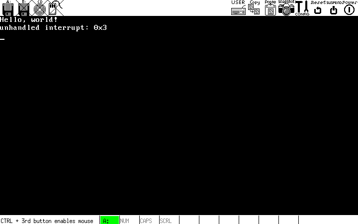
What it should look like
Congrats! You've now got a kernel that can handle interrupts, and set up its own segmentation tables (a pretty hollow victory, considering all that code and theory, but unfortunately there's no getting around it!).
The sample code for this tutorial can be found here.